
MoCA 1.1 Reference Specification
This page describes MoCA specifications for Media Access Control (MAC) throughput, connector loss, transmit power, transmitter spectral mask, transmitter spurious output, and receiver sensitivity.
MoCA Frequency Plan
MoCA channel center frequencies are specified within several MoCA frequency bands between 500 and 1500 MHz (inclusive) at increments as listed in Table 1-1. The Multimedia Over Coax Alliance has procedures for establishing additional MoCA bands based on new markets and use cases.
Table 1-1. List of MoCA Bands and Channel Center Frequencies
| MoCA Band | MoCA Channel Number | Channel Center Frequency [MHz] |
|---|---|---|
| A | A1 | 875 |
| B | B1 | 900 |
| C1 | C1 | 925 |
| C2 | C2 | 950 |
| C3 | C3 | 975 |
| C4 | C4 | 1000 |
D | D1 | 1150 |
| D2 | 1200 | |
| D3 | 1250 | |
| D4 | 1300 | |
| D5 | 1350 | |
| D6 | 1400 | |
| D7 | 1450 | |
| D8 | 1500 | |
E | E1 | 500 |
| E2 | 525 | |
| E3 | 550 | |
| E4 | 575 | |
| E5 | 600 | |
F | F1 | 675 |
| F2 | 700 | |
| F3 | 725 | |
| F4 | 750 | |
| F5 | 775 | |
| F6 | 800 | |
| F7 | 825 | |
| F8 | 850 | |
G | G1 | 500 |
| G2 | 550 | |
| G3 | 600 | |
| G4 | 650 | |
| G5 | 700 | |
| G6 | 750 | |
| G7 | 800 | |
H | H1 | 975 |
| H2 | 1000 | |
| H3 | 1025 |
MAC Throughput
For flat channels between any two Intermediate Devices with > 90 Mbps external interfaces (such as 100 Mbit Ethernet) in a MoCA Network, with 1518 byte packets coming into the ECL from outside the MoCA Network, MAC Rate at a PHY Rate MUST be greater than the corresponding Minimum MAC Rate value shown in Table 1-2.
Table 1-2. Minimum MAC Rate as a Function of PHY Rate
PHY Rate (Mbps) | Minimum MAC Rate (Mbps) |
|---|---|
| ≥ 275 | 139.87 |
| 250 | 130.78 |
| 225 | 119.45 |
| 220 | 107.74 |
| 175 | 95.64 |
| 150 | 81.98 |
| 125 | 68.32 |
| 100 | 54.65 |
| 75 | 39.82 |
Connector and Return Loss
The RF input connector for a Node MUST be F-Type with a nominal impedance of 75 ohms. The return loss shall be ≥ 5 dB when operating in band A, B, C, or D, and ≥ 8 dB when operating in band E, F or H, measured over the frequency band of interest. (i.e., 45 MHz frequency band centered at the center of the tuned channel.)
MoCA Transmit Power
A Node MUST have a maximum output power between 4 dBm to +8 dBm when operating in band A, B, C, or D, or F, and between 1 dBm to +7 dBm when operating in band E or H, at every supported MoCA channel frequency, as measured at the RF connector at the output of any filter required by the Node for proper operation.
All transmit power is measured into a 75 ohm load.
MoCA Transmitter Spectral Mask
The spectral mask requirements apply for each MoCA band of operation in the frequency ranges specified in Table 1-3. The spectrum at the RF connector from the MoCA transmitter MUST conform to the mask specified in Table 1-4. The spectral mask from Fc50 MHz to Fc+50 MHz should be measured with the spectrum analyzer set to RBW = 300 kHz, VBW = 3 kHz, Sweep Mode = Continuous, Sweep Time = 300 msec, Video Averaging = On (100 traces), Span = 75 MHz. The measured peak power of any 300 kHz band within Fc 21.5 MHz (except for the range Fc0.931 MHz to Fc+0.931 MHz) is the 0 dBr value. For farther out spectral mask measurements, set the spectrum analyzer to:
- Start freq = the low edge of the frequency range in Table 1-3, stop freq = Fc – 50 MHz
- Start freq = Fc + 50 MHz, stop freq = the high edge of the frequency range in Table 1-3
Table 1-3. Transmitter Spectral Mask Frequency Ranges
| MoCA Band | Frequency Range |
|---|---|
| A,B,C,D | 775 MHz < f < 1525 MHz |
| E | 400 MHz < f ≤ 800 MHz |
| F | 600 MHz < f < 925 MHz |
| H | 850 MHz < f < 1160 MHz |
Table 1-4. Transmitter Spectral Mask
| Frequency Range | Output |
|---|---|
| Fc 21.5 MHz ≤ f < Fc 0.931 MHz | 3 dBr to 0 dBr/300 kHz |
| Fc + 0.931 MHz < f ≤ Fc + 21.5 MHz | 3 dBr to 0 dBr/300 kHz |
| Fc – 30 MHz ≤ f < Fc – 25 MHz | < -20 dBr/300 kHz |
| Fc + 25 MHz < f ≤ Fc + 30 MHz | < -20 dBr/300 kHz |
Fc – 50 MHz ≤ f < Fc – 30 MHz | < -40 dBr/300 kHz |
| Fc + 30 MHz < f ≤ Fc + 50 MHz | < -40 dBr/300 kHz |
| f < Fc – 50 MHz | < -45 dBr/2 MHz |
| Fc + 50 MHz < f | < -45 dBr/2 MHz |
![]()
Figure 1-1. Transmitter Spectral Mask
The MoCA transmitter MUST NOT be turned on during symbol transmissions of adjacent packets from other MoCA nodes. When a MoCA transmitter is turned on and no packets are being transmitted, the transmitted output power MUST be less than 39 dBc relative to the transmitted power when the ACMT carriers are turned-on excluding the following two allowed spurious:
- A single spurious at Fc with relative power of less than -23 dBc
- A single spurious at either Fc+25MHz or Fc-25MHz with relative power of less than -39 dBc appearing not earlier than 4.0 µs before the first sample of its PHY frame preamble is output at the F-connector, and with relative power of less than -35 dBc not earlier than 1.5 µs before the first sample of its PHY frame preamble is output at the F-connector.
A MoCA transmitter SHOULD be turned on less than 7.4 µs before the first symbol has reached 90% of its final value and SHOULD be turned off less than 1 µs after the last transmitted symbol.
RF Mode Transmitter Spurious Output
The spurious signals at the output of the MoCA RF connector MUST conform to the Table 1-5 when operating in band A, B, C, or D, to Table 1-6 when operating in band E, to Table 1-7 when operating in Band F, and to Table 1-8 when operating in band H, where the dBc value is measured relative to total transmitted signal power.
Table 1-5. Transmitter Spurious Output When Operating in Band A, B, C, or D
| Parameter | Value | Notes |
|---|---|---|
| Spurious at Fc | < -23 dBc | |
Inband spurious and noise excluding at Fc | < -39 dBc | Measured in 45 MHz band |
54 – 806 MHz spurious and noise when using A, C1, or C2 band channels | < -45 dBmV | Measured in 4 MHz BW including discretes |
54 – 864 MHz spurious and noise when using B, C3, C4, or D-band channels | < -45 dBmV | Measured in 4 MHz BW including discretes |
54 – 806 MHz discrete tones only when using A, C1, or C2 band channels | < -50 dBmV | |
54 – 864 MHz discrete tones only when using B, C3, C4 or D-band channels | < -50 dBmV | |
| Single tone ≥ 2000 MHz | < -3 dBmV | |
950 MHz to 2150 MHz spurious and noise when using A or B band channels | < 1 dBmV | Measured in 20 MHz BW including discretes. This requirement protects L-band signals when using A or B band channels. |
Table 1-6. Transmitter Spurious Output When Operating in Band E
| Parameter | Value | Notes |
|---|---|---|
| Spurious at Fc | -23 dBc | |
| Inband Spurious and Noise excluding at Fc | -39 dBc | Measured in 45 MHz band |
| 0.5 MHz to ≤ 2.1 MHz | -50 dBm/152 kHz | Reduce home networking OOB emissions to protect FSK transmissions |
| 2.1 MHz to ≤ 2.5 MHz | -78 dBm/152 kHz | Reduce home networking OOB emissions to protect FSK transmissions |
| >2.5 MHz to ≤ 3 MHz | < -40 dBm | Integrated power over the band |
| > 3 MHz to ≤ 4 MHz | ≤ -20 dBm | Integrated power over the band |
| > 800 MHz to < 950 MHz | < -55 dBm/20 MHz | |
| ≥ 950 – 2500 MHz | < -94 dBm/20 MHz | Reduce home networking OOB emissions to protect Satellite signals |
| > 2500 to 3000 MHz | -80 dBm/20 MHz | Reduce home networking OOB emissions to protect Satellite signal |
Table 1-7: Transmitter Spurious Output When Operating in Band F
| Parameter | Maximum Value | Notes |
|---|---|---|
| Spurious at Fc | -23dBc | |
| Inband Spurious and Noise, excluding at Fc | -39dBc | Measured in a 45MHz band |
| >10kHz to ≤ 1MHz | 25mV p-p at 12 ohm | |
| >1MHz to < 500MHz | < -58dBm/50MHz | |
| ≥500MHz to ≤575MHz | < -83dBm/50MHz | |
| >575MHz to < 600MHz | <-52dBm | |
| >925MHz to <950MHz | <-52dBm | |
| ≥950MHz to 3000MHz | < -94dBm/27MHz |
Table 1-8. Transmitter Spurious Output When Operating in Band H
| Parameter | Value | Notes |
|---|---|---|
| Spurious at Fc | -23 dBc | |
| Inband Spurious and Noise excluding at Fc | -39 dBc | Measured in 45 MHz band |
| 0.5 MHz to ≤ 2.1 MHz | -50 dBm/152 kHz | Reduce home networking OOB emissions to protect FSK transmissions |
| 2.1 MHz to ≤ 2.5 MHz | -78 dBm/152 kHz | Reduce home networking OOB emissions to protect FSK transmissions |
| >2.5 MHz to ≤ 3 MHz | < -40 dBm | Integrated power over the band |
| > 3 MHz to ≤ 4 MHz | < -20 dBm | Integrated power over the band |
| >4 MHz to <50 MHz | -54.2 dBm/2 MHz | Spurious and noise |
| 50 MHz to <174 MHz | -89 dBm/6 MHz | For protection of low VHF band devices |
| 174 MHz to 216 MHz | -101 dBm/6 MHz | Protect ISDB-T Rx |
| >216 MHz to <470 MHz | -53 dBm/6 MHz | Protect ISDB-T Rx from spurious and noise |
| 470 MHz to 806 MHz | -101 dBm/6 MHz | Protect ISDB-T Rx |
| >806 MHz to 850 MHz | -53 dBm/6 MHz | Protect ISDB-T Rx |
| >1160 MHz to < 1257 MHz | < -55 dBm/20 MHz | Protect satellite Rx adjacent channel response |
| >1257 MHz to 2500 MHz | < -94 dBm/20 MHz | Protect SWM channel frequencies and Satellite Rx signals |
| > 2500 to 3000 MHz | -80 dBm/20 MHz | Protect OOB satellite Rx spurious |
MoCA Receiver Minimum Sensitivity
The minimum receiver power at the MoCA RF input connector to reach a specified PHY Rate MUST NOT exceed that shown in Figure 1-2 and Table 1-9 when operating in band A, B, C, or D, and in Figure 1-3 and Table 1-10 when operating in band E, F or H with TPC disabled, and as shown in Figure 1-4 and Table 1-11 when operating in band F with TPC enabled, under the following conditions:
- Flat Channel
- In the presence of the following signals appearing at the input to the Node:
- When operating in bands C or D: a CATV signal as shown in Table 1-12
- When operating in band E: Simultaneously:
- An OSP Satellite transponder signal shown in Table 1-13
- An FSK control signal as show in Table 1-14
- Maximum intermittent power levels as specified in Table 1-15
- When operating in band F: Simultaneously:
- OSP Satellite Transponder Signal Level as shown in Table 1-16
- DiSEqC signal as show in
- Table 1-17
- Maximum intermittent power levels as specified in Table 1-18
- UHF Analog video signal as shown in Table 1-19
- When operating in band H: Simultaneously:
- An ISDB-T signal shown in Table 1-20
- An OSP Satellite transponder signal shown in Table 1-21
- An FSK control signal as show in Table 1-14
- Maximum intermittent power levels as specified in Table 1-22
- No other External Interference
A MoCA receiver operating in a Flat Channel MUST be able to detect beacons at a received power level of at least -76 dBm.
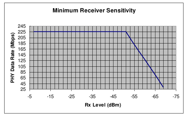
Figure 1-2. Minimum Receiver Sensitivity When Operating in Band A, B, C or D
Table 1-9. Receiver Sensitivity When Operating in Band A, B, C or D
| Min PHY Rate (Mbps) | Receive Level |
|---|---|
| 57 | -66.7 dBm (-17.95 dBmV) |
| 64.3 | -66 dBm (-17.25 dBmV) |
96.4 | -63 dBm (-14.25 dBmV) |
128.6 | -60 dBm (-11.25 dBmV) |
160.7 | -57 dBm (- 8.25dBmV) |
192.9 | -54 dBm (-5.25 dBmV) |
| 225 | -7 dBm (41.75 dBmV) to -51 dBm (-2.25 dBmV) |
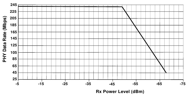
Figure 1-3. Minimum Receiver Sensitivity When Operating in Band E and F with TPC Disabled
Table 1-10. Receiver Sensitivity When Operating in Band E and F with TPC Disabled
Min PHY Rate (Mbps) | Receive Level |
|---|---|
57 | -66.1 dBm (-17.35 dBmV) |
90.2 | -63 dBm (-14.25 dBmV) |
122.3 | -60 dBm (-11.25 dBmV) |
154.4 | -57 dBm (- 8.25dBmV) |
186.5 | -54 dBm (-5.25 dBmV) |
225 | -50.4 dBm (-1.65 dBmV) |
240 | -6 dBm (42.75 dBmV) to -49 dBm (-0.25 dBmV) |
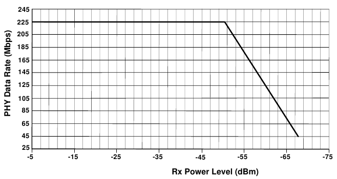
Figure 1-4: Minimum Receiver Sensitivity in Band F with TPC Enabled
Table 1-11: Minimum Receiver Sensitivity in Band F with TPC Enabled
Min PHY Rate (Mbps) | Receive Level |
|---|---|
57 | -66.1 dBm (-17.35 dBmV) |
90.2 | -63 dBm (-14.25 dBmV) |
122.3 | -60 dBm (-11.25 dBmV) |
154.4 | -57 dBm (- 8.25dBmV) |
186.5 | -54 dBm (-5.25 dBmV) |
225 | -6 dBm (42.75 dBmV) to -50.4 dBm (-1.65 dBmV) |
Table 1-12. CATV Signal Level
Parameter | Value |
|---|---|
Input Frequency range | 54-864 MHz |
RF channel spacing | 6 MHz |
Analog video carrier level (per channel) | -15 dBmV to +15 dBmV (peak envelop power in 6 MHz channel BW) |
Digital carrier level (per channel) | -15 dBmV to +10 dBmV (average power in 6 MHz channel BW) |
| Maximum number of analog carriers | 121 |
Total Power from 54-864 MHz | < 30 dBmV |
Table 1-13. OSP Satellite Transponder Signal Level
Parameter | Value |
|---|---|
Input Frequency range | 950-2150 MHz |
Signal level (in any 24 MHz bandwidth in the Input Frequency range) | Up to -20 dBm (average power per carrier) |
| Total aggregated power level (measured at the Terminal Device) | -10 dBm |
Table 1-14. FSK Control Signal
Parameter | Value |
|---|---|
Tx Carrier Frequency | 2.3 MHz ± 10 kHz |
Tx Frequency shift | ± 40 kHz +10/-5 kHz |
Asynchronous Serial Bit Rate | 39 kbaud ±0.5% |
Tx Carrier maximum Power | -1 dBm (75 ohms) |
Table 1-15. Maximum Intermittent Power Levels at the Input to the Node when Operating in Band E
Frequency | Power Level* |
|---|---|
0.2 MHz to 0.6 MHz | Increasing linearly from -31dBm/200kHz to -28dBm/200kHz |
> 0.6 MHz to 1 MHz | Increasing linearly from -28dBm/200kHz to -25dBm/200kHz |
> 1 MHz to 1.8 MHz | Increasing linearly from -25dBm/200kHz to -16dBm/200kHz |
> 1.8 MHz to 2 MHz | Increasing linearly from -16dBm/200kHz to -9dBm/200kHz |
> 2.0 MHz to 2.1 MHz | Increasing linearly from -9dBm/200kHz to -1dBm/200kHz |
> 2.1 MHz to 2.5 MHz | -1 dBm/200 kHz |
> 2.5 MHz to 100 MHz | Decreasing linearly from -1 dBm to -30 dBm/200 kHz |
> 100 MHz to 200 MHz | -35 dBm/200 kHz; -30 dBm Aggregate |
> 200 MHz to 300 MHz | -45 dBm/200 kHz; -40 dBm Aggregate |
> 300 MHz to 450 MHz | -55 dBm/200 kHz; -50 dBm Aggregate |
> 450 MHz to 470 MHz | -65 dBm/200 kHz; -60 dBm Aggregate |
> 470 MHz to 475 MHz | -96 dBm/200 kHz |
> 475 MHz to 625 MHz | -116 dBm/200 kHz |
> 625 MHz to 630 MHz | -96 dBm/200 kHz |
> 630 MHz to 650 MHz | -65 dBm/200 kHz; -60 dBm Aggregate |
> 650 MHz to 800 MHz | -55 dBm/200 kHz; -50 dBm Aggregate |
> 800 MHz to 950 MHz | -55 dBm/20 MHz |
* The power level is the measured peak power level over any 5 s time interval.
Table 1-16. OSP Satellite Transponder Signal Level at Node Input in Band F
Parameter | Value | Notes |
|---|---|---|
Input Frequency range | 950-3000 MHz | |
Signal level | -25 dBm | Per 27MHz transponder |
Total aggregated power level | -7 dBm |
Table 1-17. DiSEqC Control Signal at Node Input in Band F
Parameter | Value | Notes |
|---|---|---|
Tx Carrier Frequency | 17.6 kHz – 26.4 kHz | |
Signal level | 200 mVp-p – 1Vp-p | |
DiSEqC Impedance (DiSEqC™ Bus Specification Version 4.2 (February 25, 1998)) | 12 – 18 ohm | Rx mode |
Table 1-18. Maximum Intermittent Power Levels at Node Input in Band F
Frequency | Power Level* |
|---|---|
1 MHz < f ≤ 10MHz | -30dBm/200KHz, -13dBm aggregate |
10 MHz < f ≤ 300MHz | -35dBm/200KHz, -30dBm aggregate |
300 MHz < f ≤ 450MHz | -45dBm/200KHz, -40dBm aggregate |
450 MHz < f ≤ 625MHz | -55dBm/200KHz, -50dBm aggregate |
625 MHz < f ≤ 645MHz | -65dBm/200KHz, -60dBm aggregate |
645 MHz < f ≤ 650MHz | -96dBm/200KHz |
650 MHz < f ≤ 875 MHz | -116 dBm/200 kHz |
875 MHz < f ≤ 880 MHz | -96dBm/200KHz |
880 MHz < f ≤ 900MHz | -65dBm/200KHz, -60dBm aggregate |
900 MHz < f ≤ 950MHz | -55dBm/200KHz, -50dBm aggregate |
* The power level is the measured peak power level over any 5µs time interval.
Table 1-19. UHF Analog Signal Level at Node Input in Band F
Parameter | Value | Notes |
|---|---|---|
Input frequency range | 500 – 575MHz | |
Maximum signal power level (per channel) | -27dBm | Peak NTSC picture carrier level in 6MHz bandwidth |
Maximum number of carriers | 2 | |
Maximum aggregate power level | -24dBm |
Table 1-20. ISDB-T Signal Level
Parameter | Value |
|---|---|
Input Frequency range | 174-216 MHz and 470-806 MHz |
RF channel spacing | 6 MHz |
Digital carrier level (per channel) | -14.8 dBm (maximum power in 6 MHz) |
Maximum number of digital carriers | 30 |
Total Power from 174-216 MHz and 470-806 MHz | 0 dBm |
Table 1-21. OSP Satellite Transponder Signal Level for Band H
Parameter | Value |
|---|---|
Input Frequency range | 1257-2150 MHz |
Signal level (in any 24 MHz bandwidth in the Input Frequency range) | Up to -16 dBm (average power per carrier) |
Total aggregated power level (over the full band measured at the SWM LNB output) | -6.5 dBm |
Table 1-22. Maximum Intermittent Power Levels at the Input to the Node When Operating in Band H
Frequency | Power Level* |
|---|---|
0.2 MHz to 0.6 MHz | Increasing linearly from -31dBm/200kHz to -28dBm/200kHz |
> 0.6 MHz to 1 MHz | Increasing linearly from -28dBm/200kHz to -25dBm/200kHz |
> 1 MHz to 1.8 MHz | Increasing linearly from -25dBm/200kHz to -16dBm/200kHz |
> 1.8 MHz to 2 MHz | Increasing linearly from -16dBm/200kHz to -9dBm/200kHz |
> 2.0 MHz to 2.1 MHz | Increasing linearly from -9dBm/200kHz to -1dBm/200kHz |
> 2.1 MHz to 2.5 MHz | -1 dBm/200 kHz |
> 2.5 MHz to <30 MHz | Decreasing linearly from -1 dBm to -21 dBm/200 kHz |
> 30 MHz to <45 MHz | Decreasing linearly from -21 dBm to -60 dBm/200 kHz |
> 45 MHz to <50 MHz | -60 dBm/200 kHz |
50 MHz to < 174 MHz | -89 dBm/6 MHz |
| 174 MHz to 216 MHz | -99 dBm/6 MHz |
> 216 MHz to 470 MHz | -60 dBm/200 kHz; -55 dBm Aggregate over the full band |
> 470 MHz to 806 MHz | -99 dBm/6 MHz |
> 806 MHz to 925 MHz | -55 dBm/200 kHz; -50 dBm Aggregate over the full band |
> 925 MHz to 945 MHz | -65 dBm/200 kHz; -60 dBm Aggregate over the full band |
> 945 MHz to 950 MHz | -96 dBm/200 kHz |
> 950 MHz to 1050 MHz | -116 dBm/200 kHz |
> 1050 MHz to 1080 MHz | -96 dBm/200 kHz |
>1080 MHz to 1100 MHz | -65 dBm/200 kHz; -60 dBm Aggregate over the full band |
>1100 MHz to 1175 MHz | -55 dBm/200 kHz; -50 dBm Aggregate over the full band |
>1175 MHz to 1257 MHz | -55 dBm/20 MHz |
>1257 MHz to 2150 MHz | -94 dBm/20 MHz |
>2150 MHz to 2500 MHz | -94 dBm/20 MHz |
>2500 MHz to 3000 MHz | -80 dBm/20 MHz |
* The power level is the measured peak power level over any 5µs time interval.
Abbreviations
Table 1-23. Table of Abbreviations
| Term | Stands for |
|---|---|
| ACMT | Adaptive Constellation Multi-tone |
| APM | Added PHY Margin |
| CRC | Cyclic Redundancy Checksum |
| ECL | Ethernet Convergence Layer |
| FSK | Frequency Shift Keying |
| ISDP-T | Integrated Services Digital Broadcasting Terrestrial |
| LMO | Integrated Services Digital Broadcasting Terrestrial |
| LNB | Low Noise Block down-converter |
| MAC | Media Access Control |
| MoCA | Multimedia over Coax Alliance |
| OSP | Operator-Service Provider |
| PHY | Physical Layer |
| RBW | Resolution Bandwidth |
| SWM | Single Wire Multi-switch |
| VBM | Video Bandwidth |
Definitions
Flat Channel – A MoCA channel with power magnitude variation of less than 4.5 dB and group-delay variation of less than 2 ns across any MoCA channel with no added noise, interference, or multipath.
Intermediate Device – An Intermediate Device is a MoCA node that has as one of its primary functions bridging of user content between the MoCA Network and an external device over an industry standard interface such as Ethernet or USB.
Terminal Device – A Terminal Device is a MoCA node whose primary function is to source or sink user content over the MoCA Network. A set-top box is an example of a Terminal device.